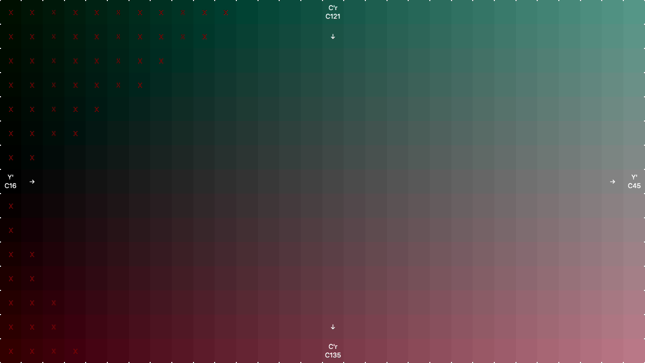
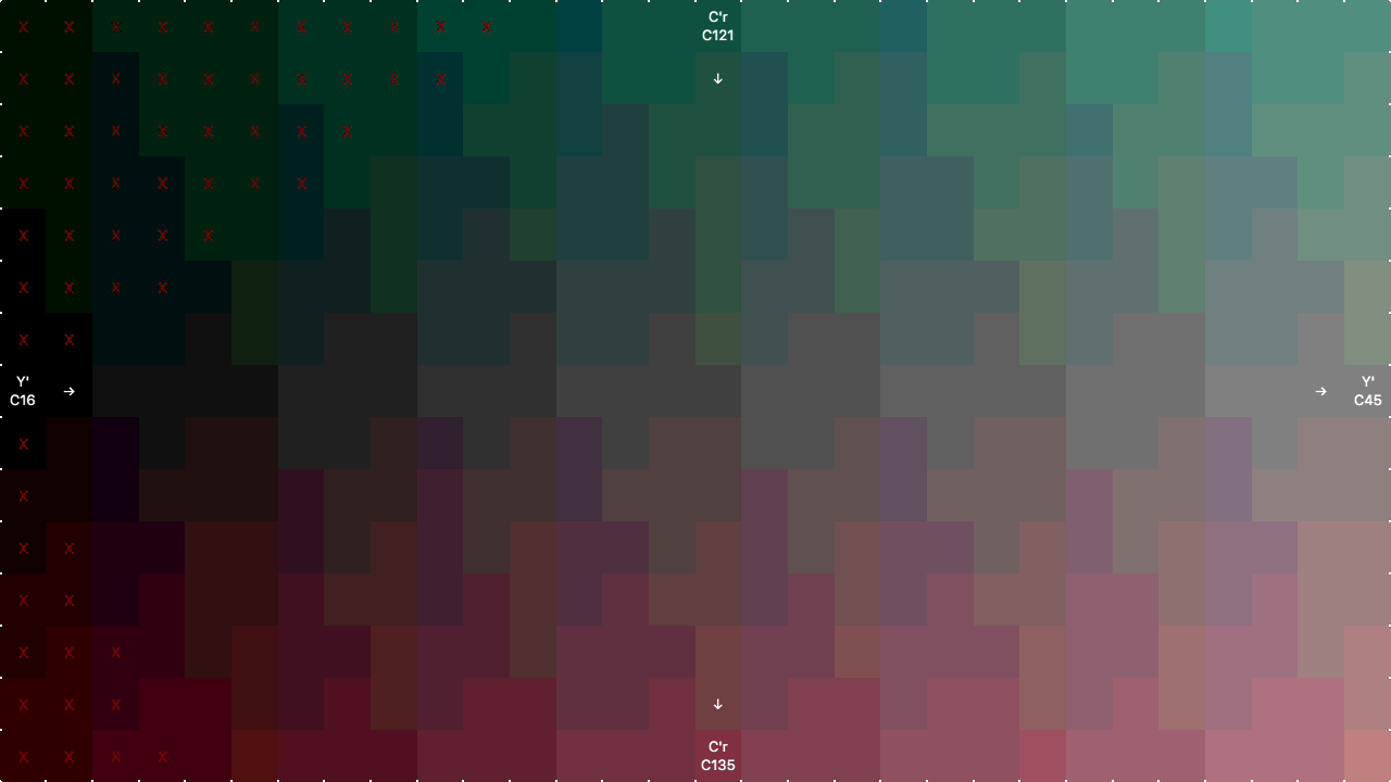
This test pattern displays two dimensional quantization grid. On the horizontal axis there is luma (Y’ channel) with 30 evenly spaced steps of 1 LSB (least significant bit). On the vertical axis there is chroma (C’b or C’r channel) with 15 evenly spaced steps of the same 1 LSB per step, other chroma channel is fixed at its corresponding achromatic value. There are markings on edges of the screen that show where the steps are separated. Some patterns also contain X markings - those denote cells that will be clipped when converting to the RGB space.
This pattern is very good at testing local nonlinearity artifacts introduced by media players and TV processing. Lack of linearity on this scale leads to visible color banding (posterization) artifacts on real world pictures/videos. This is the reason of contouring artifact on static images with slow smooth gradients and moving bands on object or flickering details during slow smooth scene lighting changes.
Bellow are some samples of good and bad rendering of Quants2D set of test patterns. We have chosen the near-black pattern as the most representative in the set and often most problematic on actual TV sets. For the sake of clarity when displaying on web page we amplify here intensity of the pattern 4 times, it is supposed to be watched in dark room on the real TV screen and will be dim compared to pictures bellow).
The reference
The main criteria of correct rendering of the pattern is a visually smooth increase of brightness in cells from left to right sides of the screen and also visually smooth change in color from top to bottom. Any grouping or appearance of visually sticking zones of cells or structures larger than one cell is a signal of visible non-linearities in a playback chain.
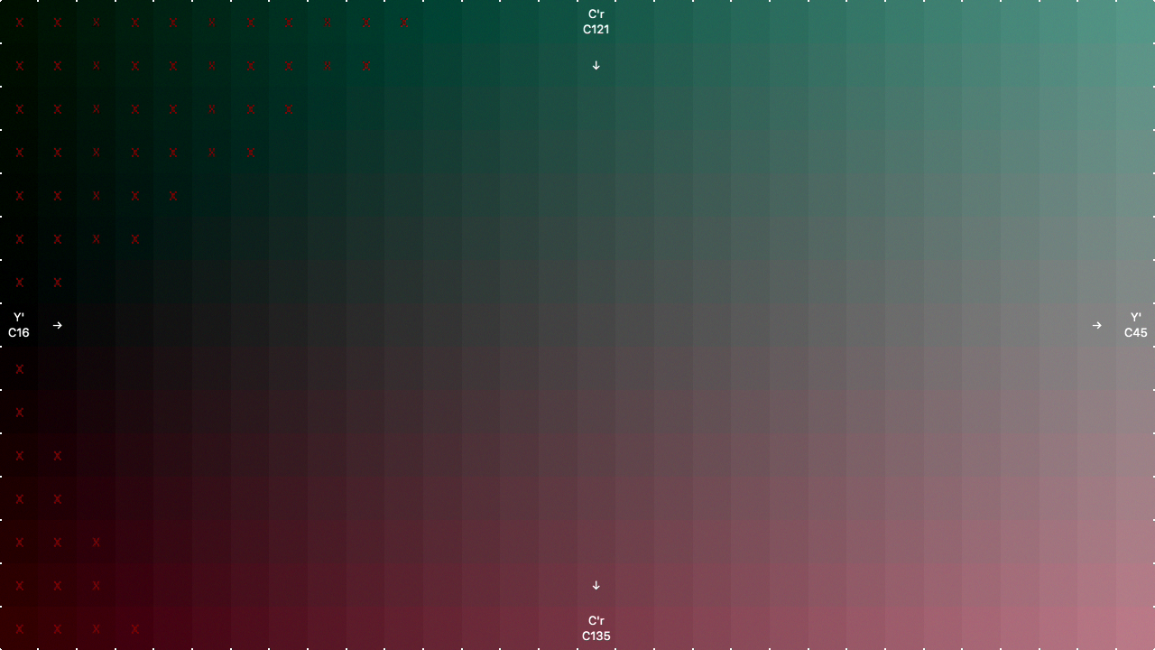
8 bit YUV to 10 bit RGB
The above is the example of rendering of the pattern to higher-resolution screen with truncation at the last step. If you are really picky you may see some inhomogeneities here, but they are very minor and not a subject on a real display with a real video or photographic content.
8 bit YUV to 8 bit RGB dithered
Here is another example of rendering the pattern to the RGB of the same bitdepth, but this time dithering is used before rounding values to the target RGB space. You may see that this picture is very similar to the previous one, and you need a hard look to find the differences. What you may find if you are picky is that this picture have even smoother distribution of color per step, but there is slight amount of noise added. We just used plain TPDF dithering to render this picture, it is very simple and cheap algorithm and doesn’t provide benefits of visually reducing the noise of more complex noise-shaping algorithms, but still it’s presence is very slightly noticeable.
But remember, sample pictures are amplified so is the noise added to the picture (efficiently you see it as if your computer screen would have only 6 bit). So, in both examples any visible artifacts are not a problem and both them can be told as representing the reference display behavior and also both can be considered as a perfect rendering of the pattern.
Not as good to epic fail examples
Le’t now review how it may look if media player of TV doesn’t do perfect math in the video chain.
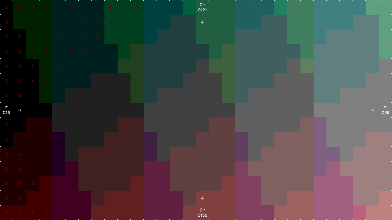
8 bit YUV to 8 bit RGB truncated (satisfying)
In the above example we have just rendered it to RGB and rounded it to 8 bit without dither. When comparing it to two previous exapmles you immediately notice something is not well with it. So, even when the target bitdepth is equal to the source color shift artifacts appeared are immediately obvious due to undithered rounding. You see cells on the pattern are visually grouping together in larger blocks than the cell size. And while there is still separate color in each cell and they do not blend one into another it may still introduce slight posterization when rendering even perfectly coded gradient.
While this is not ‘end of the world’ and the result might be quite tolerable this is already not a videophile quality. Although you will rarely see it better on a real device.
So, let’s see what happens when even more resolution is lost due to (improper) computations on the example of further bitdepth reduction…
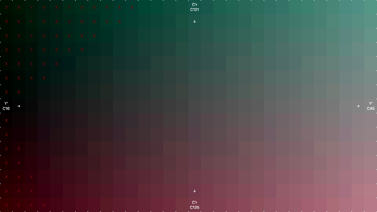
8 bit YUV to 7 bit RGB truncated (bad):
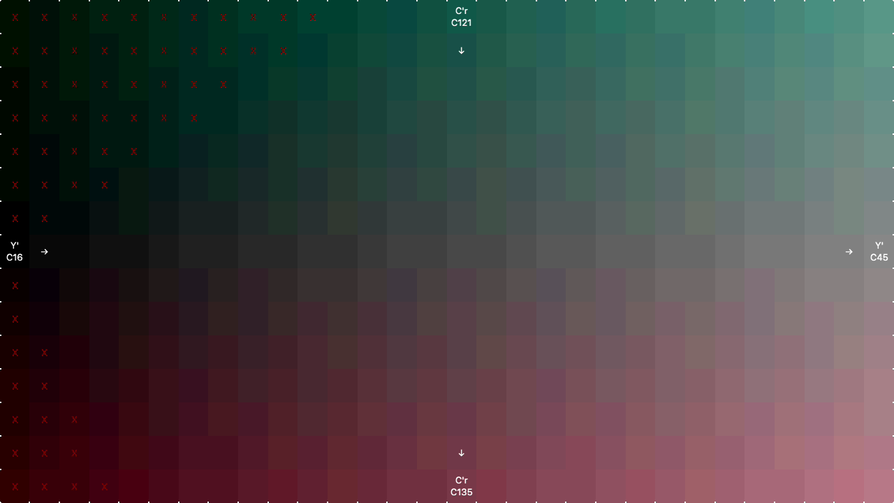
8 bit YUV to 6 bit RGB truncated (worse):
8 bit YUV to 5 bit RGB truncated (terrible):
So, you see here is already cells blending one into another into single color groups. This is not nearly acceptable on any video reproduction device, but even worse things than presented on the last pattern above are happening on a real consumer television sets, even some ‘high-end’ TVs.
Don’t believe this can be true? This is our HRD10 version of the Quants2D pattern as displayed on an LG OLED77G7V:
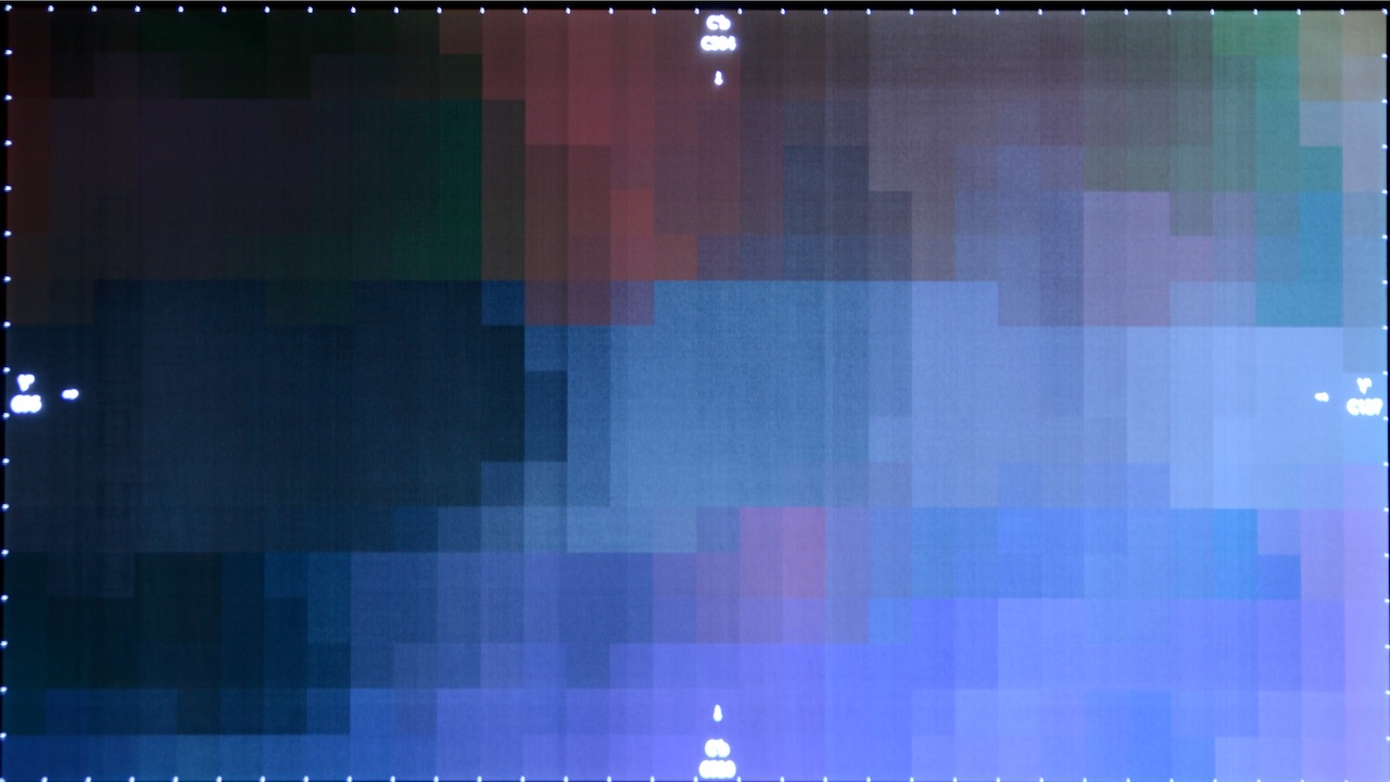
Epic fail to say the least! 2016 LG OLEDs expose similar performance in 10 bit modes. There is no surprise there are so many complaints about color banding and posterization on these sets.
We really believe that adding such test pattern to a set of evaluation procedures already used by TV reviewers will let us get better TVs in the end.